


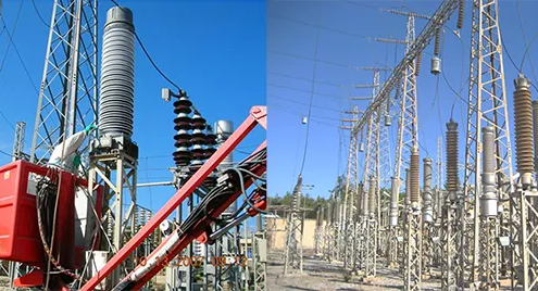
 https://jaipuriabrotherselect.com/wp-content/uploads/2026/04/Substations.webp
268
700
manager
https://jaipuriabrotherselect.com/wp-content/uploads/2025/02/jaipuria-brothers-logo.png
manager2026-04-08 07:58:532026-04-08 08:06:46High-Quality 132 kV Isolators for Reliable Power Infrastructure By Jaipuria Brothers Electrical
https://jaipuriabrotherselect.com/wp-content/uploads/2026/04/Substations.webp
268
700
manager
https://jaipuriabrotherselect.com/wp-content/uploads/2025/02/jaipuria-brothers-logo.png
manager2026-04-08 07:58:532026-04-08 08:06:46High-Quality 132 kV Isolators for Reliable Power Infrastructure By Jaipuria Brothers ElectricalSpare for isolators upto 400 kv
Our latest line of premium spare parts for isolators up to 400 kV, Key Spare Parts Available.


Bestsellers
We are offering Polymer Insulator, Post Insulator, Air Break Switches, PG Clamps, Lightning Arrester, Electrical Isolator, Drop Out Fuse etc

Disc Insulators

Polymer Pin insulator

Polymer Disc Insulator

Polymer LA

11 kv Air Break switch

PG Clamp

11kv dropout fuse

33kv 400a rotating isolator
Earthing Materials

Tension Clamps

Air Break Isolating Switches

Lightning Arrestors

Gi Strip For Earthing

33 Kv Isolator With Earth Polymer

Porcelain Pin Insulator 11Kv
Welcome to the Official Website of JAIPURIA BROTHERS ELECTRICALS PVT LTD.
We, Jaipuria Brothers Electricals Pvt. Ltd, manufacture an extensive range of electrical equipment, earthing materials, earthing strips, earthing wires, rubber products and electrical accessories that are used throughout in the power sector & distribution networks. We are an ISO 9001 certified company catering to a large number of companies in the energy sector. Established in 1974, we are engaged in supplying of various electrical equipment for the material handling and transmission & distribution systems for industrial, commercial and residential sectors.
Leveraging on our long industry standing, we have executed design, supply & fabrication of 2,4 & 6 pole electrical crossing between Qazigund Baramullah work Rs. 6 crore. We are also executing design, supply, erection, testing & commissioning of 11 & 33 kv substation on 15 railway stations in J & K. This work is worth around Rs. 4 crore. Furthermore, we have also diversified our operations into turnkey project execution of electrical jobs in transmission, lines, sub-stations and industrial electrification.
We emphasize on improving our products & process in order to become synonymous with top-notch quality and world-renowned excellence.
Customers
What Our Customers Say
I would like to take this opportunity to say that the quality of service offered by Jaipuria Brothers, our first contact over a year ago has been highly impressive. Every aspect of your service has been beyond reproach and every member of staff has been courteous, polite and reliable.
It has again been a pleasure dealing with Jaipuria Brothers and I appreciate your helpfulness and flexibility.
It has again been a pleasure dealing with Jaipuria Brothers and I appreciate your helpfulness and flexibility.
https://jaipuriabrotherselect.com/wp-content/uploads/2026/04/Substations.webp
268
700
manager
https://jaipuriabrotherselect.com/wp-content/uploads/2025/02/jaipuria-brothers-logo.png
manager2026-04-08 07:58:532026-04-08 08:06:46High-Quality 132 kV Isolators for Reliable Power Infrastructure By Jaipuria Brothers Electrical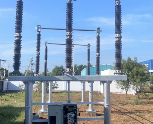 https://jaipuriabrotherselect.com/wp-content/uploads/2025/10/2343.jpg
1600
900
manager
https://jaipuriabrotherselect.com/wp-content/uploads/2025/02/jaipuria-brothers-logo.png
manager2025-10-04 10:29:102025-10-04 10:40:46Enhance Power System Reliability with Spare Parts for Isolators 400 kV
https://jaipuriabrotherselect.com/wp-content/uploads/2025/10/2343.jpg
1600
900
manager
https://jaipuriabrotherselect.com/wp-content/uploads/2025/02/jaipuria-brothers-logo.png
manager2025-10-04 10:29:102025-10-04 10:40:46Enhance Power System Reliability with Spare Parts for Isolators 400 kV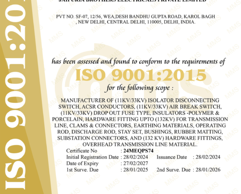 https://jaipuriabrotherselect.com/wp-content/uploads/2025/03/system.png
1697
1200
manager
https://jaipuriabrotherselect.com/wp-content/uploads/2025/02/jaipuria-brothers-logo.png
manager2025-09-19 10:41:372026-04-08 08:49:11Why Certification Matters: Your Assurance of Quality and Safety with Jaipuria Brothers Electrics
https://jaipuriabrotherselect.com/wp-content/uploads/2025/03/system.png
1697
1200
manager
https://jaipuriabrotherselect.com/wp-content/uploads/2025/02/jaipuria-brothers-logo.png
manager2025-09-19 10:41:372026-04-08 08:49:11Why Certification Matters: Your Assurance of Quality and Safety with Jaipuria Brothers Electrics https://jaipuriabrotherselect.com/wp-content/uploads/2025/06/grid.png
412
617
manager
https://jaipuriabrotherselect.com/wp-content/uploads/2025/02/jaipuria-brothers-logo.png
manager2025-06-23 12:31:422025-06-23 12:31:43India’s Trusted Partner for 400/220 kV GIS Substation Equipment — Jaipuria Brothers Electricals Pvt. Ltd.
https://jaipuriabrotherselect.com/wp-content/uploads/2025/06/grid.png
412
617
manager
https://jaipuriabrotherselect.com/wp-content/uploads/2025/02/jaipuria-brothers-logo.png
manager2025-06-23 12:31:422025-06-23 12:31:43India’s Trusted Partner for 400/220 kV GIS Substation Equipment — Jaipuria Brothers Electricals Pvt. Ltd.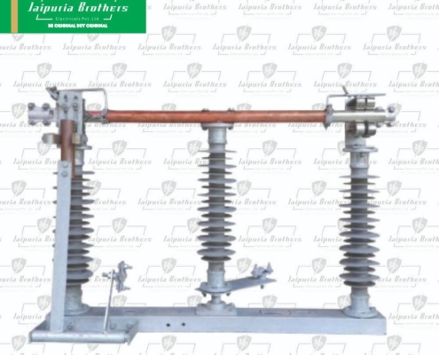 https://jaipuriabrotherselect.com/wp-content/uploads/2025/06/33kv-isolator.jpg
1000
1000
manager
https://jaipuriabrotherselect.com/wp-content/uploads/2025/02/jaipuria-brothers-logo.png
manager2025-06-05 12:40:322026-04-16 11:05:47Why 33kV Isolators Are Essential for Medium Voltage Systems – And Why Jaipuria Brothers Is Your Best Choice in India
https://jaipuriabrotherselect.com/wp-content/uploads/2025/06/33kv-isolator.jpg
1000
1000
manager
https://jaipuriabrotherselect.com/wp-content/uploads/2025/02/jaipuria-brothers-logo.png
manager2025-06-05 12:40:322026-04-16 11:05:47Why 33kV Isolators Are Essential for Medium Voltage Systems – And Why Jaipuria Brothers Is Your Best Choice in India https://jaipuriabrotherselect.com/wp-content/uploads/2025/05/power-grid-stability.png
488
743
manager
https://jaipuriabrotherselect.com/wp-content/uploads/2025/02/jaipuria-brothers-logo.png
manager2025-05-28 16:59:292025-05-28 17:18:04Ensuring Grid Stability: The Role of High-Voltage Isolators in India’s Power Infrastructure
https://jaipuriabrotherselect.com/wp-content/uploads/2025/05/power-grid-stability.png
488
743
manager
https://jaipuriabrotherselect.com/wp-content/uploads/2025/02/jaipuria-brothers-logo.png
manager2025-05-28 16:59:292025-05-28 17:18:04Ensuring Grid Stability: The Role of High-Voltage Isolators in India’s Power Infrastructure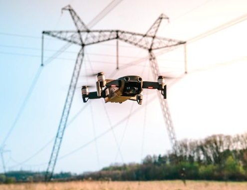 https://jaipuriabrotherselect.com/wp-content/uploads/2025/04/ai.jpg
381
678
manager
https://jaipuriabrotherselect.com/wp-content/uploads/2025/02/jaipuria-brothers-logo.png
manager2025-04-30 12:32:452025-04-30 12:35:00AI and Drones in India’s Power Transmission Revolution
https://jaipuriabrotherselect.com/wp-content/uploads/2025/04/ai.jpg
381
678
manager
https://jaipuriabrotherselect.com/wp-content/uploads/2025/02/jaipuria-brothers-logo.png
manager2025-04-30 12:32:452025-04-30 12:35:00AI and Drones in India’s Power Transmission RevolutionRegistered with


